INGETEAM
ECONO V + ADAPTER ASSEMBLY
ECONO V + ADAPTER ASSEMBLY
Couldn't load pickup availability
ECONO V + ADAPTER ASSEMBLY
TESTING SUMMARY
- Adapter board testing to confirm the functionality of the board including the Switching time and power supply voltage measurements.
- IGBT Module Diode Characterization testing to rated current.
- IGBT Module IGBT Characterization testing to the rated current
- IGBT Module Switching characterization testing to the switching Specifications.
- IGBT module Power switching functional testing at Converter rated switching frequency.
DATASHEET
DESCRIPTION
- Brand new power module for Ingeteam converters fully compatible with installed modules
- New Infineon-IGBTs
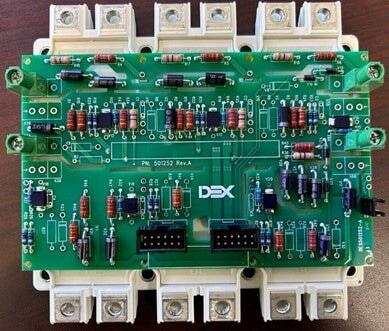
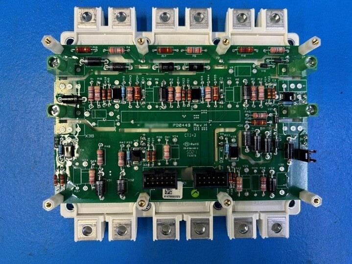
The module AK9785 consists of
- A semiconductor module type FS450R17OP4, composed of a pack of six IGBTs and its diodes in antiparallel.
- An adapter card, which allows to trip the semiconductors in two groups of three switches connected in parallel. This electronic card adapts the triggering signals generated by a driver card and sends them to the gates of the corresponding IGBTs.
CHARACTERISTICS
Technical
Table 1 - Technical Characteristics
|
IGBT Module IGBT Nominal Current |
1350 A |
|
IGBT Maximum Voltage |
1700 V |
|
Gate-Emitter Voltage |
±15 V |
Mechanical
Table 2 - Mechanical Characteristics
|
Mechanical Dimensions (A) (Length x Width x Depth) |
162 x 150 x 47 mm |
|
Weight (A) |
1.1 Kg |
AMBIENT CONDITIONS
Table 3 - Climatic Technical Data
|
Operation temperature |
-25 ºC a 60 ºC |
|
Storage temperature |
-40 ºC a 70 ºC |
|
Relative humidity |
< 95% |
CONNECTIONS
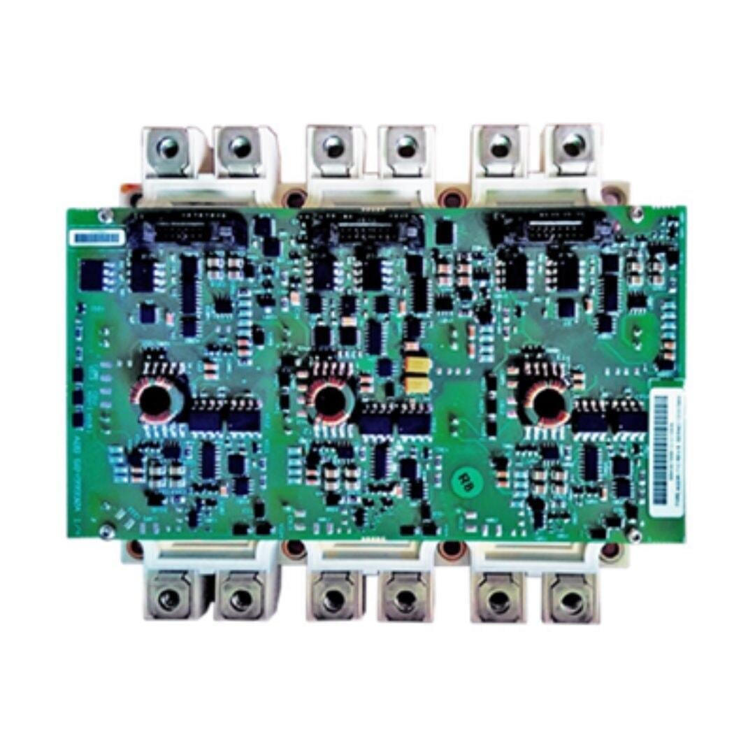
The semiconductors are connected as shown in the next image, the three TOP switches in parallel and the three BOTTOM switches in parallel.
To parallelize two or more modules, apart from the power connections between the modules, it is necessary to connect the desaturation protection. For this interconnection, the side connectors of the adaptation card (X2A, X3A or X5A, X6A) must be used.
Connections
Table 4 - Connections
|
Terminals 1,3 and 5 |
‘-’ bar of the DC_Bus |
|
Terminals 2, 4 and 6 |
‘+’ bar of the DC_Bus |
|
Terminals 7 to 12 |
Output / Phase bars |
|
X2A, X5A |
Common collector IGBT TOP |
|
X3A, X6A |
Common collector IGBT BOTTOM |
MODULE MOUNTING RECOMMENDATIONS
Table 5 - Module Mounting
|
Mounting Torque for the module |
3,5 Nm |
|
Terminal Connection Torque |
4,5 Nm |
Recommend way of module mounting to Heatsink Clamping:
- Initial: 1/3 specified mounting torque. Sequence: (1)→(2)→(3)→(4)→(5)→(6)→(7)→(8)
- Final: Full specified mounting torque. Sequence: (4)→(3)→(2)→(1)→(8)→(7)→(6)→(5)
HANDLING INSTRUCTIONS
TRANSPORT
Some cautions must be taken when the module is in transport. Any abrupt shock or drop can produce damages on the module’s internal components.
It´s recommended for its manipulation, to introduce the module into an antistatic bag. This operation protects it against beats and electrostatic discharges over their internal components, which could cause of its destruction.
RECEPTION
At the time of reception, an external visual inspection must be realized over the module, in order to detect any damage during the transport stage.
In case of detecting any problem in the module, it’s recommended to notify the act to the provider and to the transport company immediately, indicating the serial number / model of the affected product and the ordering number.
PACKAGING AND STORAGE
The modules are packed individually in carton boxes, with an internal layer of protection inside them. These boxes must be marked with the serial number of the final product and the module reference which is inside the box.
The boxes must be marked as fragile product.
If the module is not immediately installed after the reception, these points must be taken into consideration to avoid problems:
- Maintain the module free of dust, shavings, grease... etc., as well as rats.
- Protect the module against projected water, welding sparks, etc.
- Cover the module with a breathable material to prevent condensation due to ambient humidity.